


31 Mar Sicass Front LED Replacement // KTM 3-Fiddy
This post I’ll be installing Sicass Racing Front LED Turn Signals my 2017 KTM 350 EXC-F!
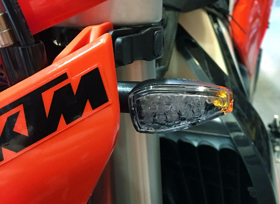
Sicass Racing Front LED Turn Signal Kit
For me the stock turn signals were just too big, and they would surely get ripped off the first trail ride out.. so I found a set that are exactly like the signals I had on my WR250R except they come from Sicass with stock wire connectors already on them. Once again from Sicass, truly plug-n-play…. keep reading!
Now, there are a few things that MUST be done to the EXC-Fs if you have gotten rid of all the bulb turn signals as I have. All my turn signals are now LEDs. The rear of my KTM has been replace with the PW Tail Kit which is awesome! A new flasher and a slight modification to the signal wiring. If you do not install the Indicator Wiring Kit, when you turn your signal on, ALL of your turn signals will flash at the same time.
Here’s the part numbers from Sicass Racing:
- Clear Lens LED – KTM / FE / FE-S (Part #: 22-102c)
- Sicass Smart Flasher – LED Turn Signal Flasher (Part #: 22-300)
- KTM/Universal Turn Signal Indicator Wiring (Part #: 22-299)
If you purchase these parts from Sicass Racing, they include color photo instructions which are pretty good. Here you will be able to see larger photos and see how even I completed this install!
The Indicator Wiring kit is needed because “the KTM EXC’s back-feed through the OEM indicator, this wiring kit corrects this issue and allows you to run LED turn signals and still use your stock turn signal indicator that is located on the dash board.”
I’ve installed all of this and it works without a hitch.. here’s a summary how-to of my installation.
1. New Flasher
First, take the headlight assembly off. Install the new flasher, simply unplug the stock flasher and plugin the new one.

2. Mounting New Flasher
Here’s where I mounted the new flasher so it’s out of the way.. has worked very well to. Simply remove one of the headlight screws and attach the new flasher with the mounting screw!

3. Indicator Wiring Kit
Here’s the parts included in the wiring kit. You will need some crimpers and wire cutters. If you plan to solder, nows a good time to get it heated up!

4. Installing Wiring Kit
This install is not a plug-n-play, you need to be comfortable with wiring, crimping, etc. I solder all of my connectors just for that extra assurance. Don’t worry the instructions Sicass includes are pretty good with color photos. But I thought I’d show my steps as well.

5. Remove Indicator Bulb
Grab the black gromet at the bottom of the indicator and the bulb will come out.

6. Bulb Removed
Here is the bulb out of the socket, just be careful when pulling on these wires as they are very small gauge.

7. Indicator Bulb Wiring
Following the bulb wiring down, a purple and black wire. With scissors, slice the wiring housing up about 2″ or so. You need to expose the wiring to cut it and add terminals to it.

8. Cut Black Wire
Cut the BLACK wire about 3″ from the base of the bulb and grommet.

9. Terminate Black Wire
With the wire cut, slide the included rubber insulator boot on the wires FIRST! A female connector is terminated on the bike side & male connector is terminated to the bulb side.

10. Solder Black Wire
Optionally, you can solder the connectors. I like to do this on all my electrical connections just to be sure I won’t be on the trail and a wire come loose.

11. Connect Y to Black
Now connect one of the yellow male connectors on the included YELLOW wiring to the black female connector you just terminated on the bike side. Slide the insulation boots over the connector.

12. Connect Ground Ring Wire
Connect the included ground wire with the ring connector on it to the black wire on the bulb side you just terminated. Slide the insulation boots over the connector.

11. Cut & Terminate Purple Wire
Take the purple wire from the bulb and cut it just like the black wire. Terminate a female connector on the bike side and a male connector on the bulb side. Optionally, solder the connectors to the wire.
Connect the other YELLOW male connector on the Y wire to the purple female connector.

12. Connect Red Wire
Next, connect the red wire at the end of the yellow Y wire to the purple wire on the bulb side. Slide the insulation boots over the connector.
Below you can see all of the wires connected.

13. Tape Up Connections
To protect the connectors and wiring from the elements, I wrapped the kit up with electrical tape.
This also helps isolate the wiring and is less of a rats nest behind the headlight assembly.

14. Finally, Ground It!
The wire ring must be ground to the bike. I ground mine to the mounting bolt of the voltage regulator on the left side of the frame. Make sure you allow for enough slack to allow the bars to turn fully in both directions.

That’s it! Test everything, make sure its working correctly. Carefully tuck your wires up and reinstall the headlight assembly… Now those turn signals will be enough for the little street riding this bike will see and won’t get broken the first drop! Ride Safe!
No Comments